SKILL_SHOT
Banned
- Jul 11, 2012
- 3,659
- 1
I enterd PINSIDE for 10% discount.
")
Alot brighter. Where the flashers out before? Looks good Now the fun part


Hopefully these DIY’s will save you a few bucks over the pre-assembled
mods which can run from $50-$100 each. Probably won’t garner me any love
with the mod sellers but who cares. The processes are very simple and
even if you aren’t that skilled with wiring/electronics you can complete
these mods without a problem so don’t be scared!

If you have any questions during the process please feel free to drop me
an email.


I looked for the pictures I had taken the last time I did this and
couldn't find them (I probably deleted them already) so I took my last
Hallmark Warbird and went to town on it specifically for DIY
photos/instructional purposes.

Something I noticed while I was paying much closer attention this time
is that the lights in the Romulan Warbird aren't LED's, they are little
tiny incandescent bulbs. You can see one here:
http://i50.photobucket.com/albums/f3...G/IMG_4333.jpg
There is a reason you can hook up the Klingon Bird of Prey directly to
the existing GI bulb sockets and it works 100%.... because that ship
only uses LED's to create its lighting effects. If you attempt to hook
up the Warbird (or the enterprise for that matter) directly to a GI
string, there is virtually no light (if any) emitted at all from the
warp nacelles . The current required to run the 4 incandescent bulbs is
much more than a circuit already filled with a string of other
incandescent bulbs can handle. This realization leaves you with two
options and one is more time consuming and complicated than the other.


DIY 1st method:
As far as the Romulan Warbird goes, the first and more complicated
option is to keep the incandescent bulbs inside the ship and remount the
circuit board under the PF. The items required for this install are as
follows: 8 wire male and female Molex connectors/terminals (2 rows of 4
work best), 1 ¼” hole saw, some black and red 22ga wire, 1.5mm heat
shrink tubing, 5mm heat shrink tubing, zip ties:

Instructions:
The first step is to separate the top and bottom halves of the ship.
You’ll need a sharp razor blade or Exacto knife and cut along the back
of the ship as pictured here:
http://i50.photobucket.com/albums/f3.../IMG_4314a.jpg
Cut on both sides of the back metal screw post until all the
plastic/glue has been severed. Once that is done the top and bottom will
be somewhat loose in the back and you just need to give it some pressure
to separate it. Once the back has been separated you can use it as
leverage to separate the warp nacelles on both sides which also have a
metal screw post going down the center of each(so be careful). The small
front piece may or may not be glued in, if it isn’t glued then it has a
hook on the end so just back it out of the hole. If it is glued and it
accidentally breaks off not to worry, in all likelihood it won’t be
noticeable once you re assemble it as long as it’s a clean break and you
don’t mess with it. Now you will need to separate the inner and outer
pieces of the bottom half you just removed from the Warbird. This step
will allow you access to the circuit board that contains the circuitry
to allow the 4 incandescent lights to run on a Christmas tree light
string which is usually about 3-5V depending on how many lights are on
the string (similar voltage to the GI string you will be tying into).
Once you have the leads for all 4 lights and the 2 power wires cut off
at the board you will have to carefully remove the circuit board from
the ship and set it aside. Remove the green power wires (which is
knotted at the grommet so pull it through from the inside) and cut away
the green plastic grommet.

Now that the circuit board has been removed you can snap your two pieces
of the bottom half back together and cut your flasher hole through the
bottom of the ship. Make sure you tuck your yellow lead wires from the
incandescent bulbs away or the saw will rip them right off the bulb. You
will need a 1 ¼” hole saw (or a spade bit, however I highly recommend
the hole saw) and center your hole to the same location the hole is on
your original. If you're using a drill press you can just hold the ship
by hand but if you’re using a hand drill you will have to be more
careful and maybe ask a second person to assist you because holding a
drill in one hand a the ship in the other is an accident waiting to happen.

Now that your hole is cut you can take out your soldering iron and heat
the contacts on the circuit board that had the power and light leads and
remove the old wire remnants. Once that is complete you will need to
solder on a few feet of wire (enough to get from the circuit board
mounting location to reach the other end of the Molex connector from the
ship) to all 8 incandescent bulb leads on the board using 1 red and 1
black for each. Then solder enough wire onto the power leads on the
board to reach your desired GI tie in from the board mounting location.
You can now use your heat shrink tubing to clean up your under PF
install if so desired but obviously make sure you do it before the next
step. Next go ahead and crimp on your terminals to the end of your bulb
leads coming from the board and insert them into the Molex connector.
You can now locate your board under the PF in a convenient location that
allows for good access and solder your power leads to the GI lamp you're
using. This should be the only soldering you have to do on the pin. Zip
tie up your wires and leave the Molex hanging for later.

Back to the disassembled Warbird. You’ll want to separate the two halves
of the bottom piece again because you are going to solder a red and
black wire from each incandescent bulb wire coming from the lights. Make
sure the wire is long enough to reach the other end of your Molex
connector under the PF(from the circuit board). Then run the 8 wires out
the old power hole you just cleared the grommet out of. You can use your
5mm heat shrink tubing now to tidy up your visible wiring. You'll next
want to attach the terminals and the Molex connector to the ends of the
wires.

As far as mounting the ship, you can use a small wood screw (pre drill
the hole first) to attach the back end of the ship to the existing metal
bracket from the original ship or if you weren’t too sloppy with your
hole saw you should have a very nice snug fit when you slide the ship
over the flasher dome. The slight pressure will keep it where you want
it even with the playfield raised into the vertical position. I prefer
this look to that of having the bracket, it appears to just be
floating/flying. You can rout the wires down the hole in the back left
of the playfield under the ramps. The top ramp has a slight indention
just to the right of the bracket that attaches it to the back board. If
you can’t get to it or you used a single row Molex connector you can
fish the wires out the diverter cut out in the back board as well.
Connect the Molex connector and turn the game on to see your new
illuminated Romulan Warbird.

Finished mod:
http://i50.photobucket.com/albums/f3...G/IMG_4341.jpg


There are many reasons this method is a pain. For one you have to remove
and re solder the very tiny circuit board without damaging anything. You
also have to solder to the wiring practically inside the ship coming
from the incandescent bulbs which only has 7 very small stands and any
significant tension will break the wire from the bulb. There is also the
matter of screwing something that's not supposed to be there to the
bottom of your PF. However I have seen people do it this way so I wanted
to include it in the DIY if that was the way you wanted to go with it.


DIY 2nd method:
The second and my preferred method is to replace all four incandescent
lights with 3mm clear LED’s. Feel free to use whatever process works
best for you, however this is the method I found to work the best after
experimenting with three different ships. For this method you’ll need 4
white LED’s, 2 wire male and female Molex connectors/terminals, 1 ¼”
hole saw, some black and red 22ga wire, and a 22ohm resistor, 1.5, 3,
and/or 5mm heat shrink tubing, zip ties: The LED’s I used are here but
you can use almost any kind you want (that being said, if they differ
from the specs on mine you may need to recalculate your resistor value):
http://search.digikey.com/scripts/Dk...ds=350-2318-nd
I would highly suggest you use this LED, the 1100mcd looks very nice in
the ship and I wouldn’t want it any dimmer/brighter.


Instructions:
While this method is similar to the circuit board method you’ll notice
some key differences that make it quite a bit easier. Step one is to
drill your flasher hole. You can drill your hole before or after
separating the top and bottom halves since there is no circuit board to
work around (I have always done it before separation). Drill your 1 ¼”
hole through the bottom piece in the same location that it is in your
original Warbird. Drill right through everything inside until you get
through the other side.

Here is a before picture:
http://i50.photobucket.com/albums/f3...G/IMG_4283.jpg
Through the bottom hull, keep going:
http://i50.photobucket.com/albums/f3...G/IMG_4288.jpg

If you drilled the hole first then separate the bottom and top halves
now. You’ll need a sharp razor blade or Exacto knife and cut along the
back of the ship as pictured here:
http://i50.photobucket.com/albums/f3.../IMG_4314a.jpg
Cut on both sides of the back metal screw post until all the
plastic/glue has been severed. Once that is done the top and bottom will
be somewhat loose in the back and you just need to give it some pressure
rocking it back and forth to separate it. Once the back has been
separated you can use it as leverage to separate the warp nacelles on
both sides which also have a metal screw post going down the center of
each. The small front piece may or may not be glued in, if it isn’t
glued then it has a hook on the end so just back it out of the hole. If
it is glued and it breaks off not to worry, in all likelihood it won’t
be noticeable once you re assemble it as long as it’s a clean break and
you don’t mess with it.

Broken piece which disappeared when reassembled:
http://i50.photobucket.com/albums/f3...G/IMG_4304.jpg

Now you should be sitting there with a separated Warbird with a hole in
the bottom piece. Pull out any remaining incandescent
lights/wiring/circuit board pieces (just give the bulbs a tug and they
will come right out). Now you need to prepare your 4 LED’s for
installation. Solder on your lengths of red and black wire (about 18”
will do fine) to the leads on the LED’s using the red for the positive
(which is the longer lead). Cut a strip of 1.5mm heat shrink long enough
to go from the very end of the LED lead to the start of the insulation
on the wire. Do this on the positive wires only, one wire is all that is
necessary and if you do it on both you will have a harder time fishing
the wires through the small holes on the bottom of the ship. Now you
should have 4 LED’s with red and black wires soldered to the lead ends
and the positive leads fully insulated. Take them and fish them FROM THE
TOP of the hole where the incandescent bulbs were located and run the
wires out the old power hole. The LED’s need to be sitting up a little
to fully extend into the warp nacelles when you put the top and bottom
back together.

LED’s fished through:
Top:
http://i50.photobucket.com/albums/f3...G/IMG_4305.jpg
Bottom:
http://i50.photobucket.com/albums/f3...G/IMG_4307.jpg
Close up left:
http://i50.photobucket.com/albums/f3...G/IMG_4302.jpg
Close up right:
http://i50.photobucket.com/albums/f3...G/IMG_4303.jpg

I then used 5mm heat shrink tubing on all the wires leaving the power
hole (which fit all 8 wires if you use 22ga). At the end of the run of
wire lengths you cut you’ll need to solder them all together to a single
black and red wire. I used 20ga for this single run but feel free to
continue to use the 22ga. You can solder the 22ohm resistor between the
4X 22ga positive(red) wires and the 1X 20ga red wire.
http://i50.photobucket.com/albums/f3...G/IMG_4332.jpg
Add some more 5mm tubing to finish covering the soldering joint and
use the 1.5mm to cover the single wires and the resistor to protect it
from shorting out on something. You can attach your Molex connectors
anywhere on the length of the two single wires. On the other side of the
Molex connector, solder the other end of your wires to the lamp socket
you plan on using and clean up your install with the wire ties up to the
Molex connector.

Next step is to test it before you put the ship back together so attach
the Molex connectors and make sure it lights up. If not then check your
connections because something is loose, if so then you can button it
back up. I only had to pressure fit the ship back together and
everything closed up just like it was before when it was glued. I prefer
this method because if something goes wrong it is very easy to open back
up and fix it. If your ship doesn’t stay together just by giving it some
pressure than you can superglue it together.

Mine being tested:
http://i50.photobucket.com/albums/f3...G/IMG_4315.jpg
http://i50.photobucket.com/albums/f3...G/IMG_4330.jpg
http://i50.photobucket.com/albums/f3...G/IMG_4329.jpg
http://i50.photobucket.com/albums/f3...G/IMG_4318.jpg


As far as mounting the ship, you can use a small wood screw (pre drill
the hole first) to attach the back end of the ship to the existing metal
bracket or if you weren’t too sloppy with your hole saw you should have
a very nice snug fit when you slide the ship over the flasher dome. The
slight pressure will keep it where you want it even with the playfield
raised into the vertical position. I prefer this look to that of having
the bracket, it appears to just be floating/flying. You can rout the
wires down the hole in the back left of the playfield under the ramps.
The top ramp has a slight indention just to the right of the bracket
that attaches it to the back board. If you can’t get to it you can fish
the wires out the diverter cut out in the back board as well. Connect
the Molex connector and turn the game on to see your new illuminated
Romulan Warbird.

Finished mod:
http://i50.photobucket.com/albums/f3...G/IMG_4341.jpg


Next I will quickly address the Klingon Bird of Prey mod. This mod is
fairly simple and straightforward since the ornament already uses LED’s
for its lighting. The only parts you will need to complete this mod is
one 6.8ohm 1/4 watt resistor, a soldering iron, and a hot glue gun.

WARNING: I have tried directly tying the ornament into the GI string and
while it appears to work fine that way, it will over heat and shut off
within about 30 minutes. It will actually get hot enough to melt the hot
glue holding the bulb sockets and mounting rod, just to give you an idea
of how hot it will get. While the ship will eventually cool off and
start working again, this is not the way you want your Bird of Prey
wired unless you only plan on ever having your pin on for 10 minutes at
a time.

The first step is to disconnect the old BOP from under the PF via the
two prong Molex connector with the solid green and white/green wires and
remove it from the game. Next unscrew the lamp socket from each wing and
the metal stand from the center.

Here you will need to pick a design for the lights you like the best. If
you want the rear of the ship facing the player and the front pointing
up the ramp you can have the bulbs facing the player and put red or
white bulbs in them for a thruster effect or you can keep them like they
were and face them towards them outer end of the wings. I personally
don’t see the sense in doing all the work to replace ships just to stare
at the rear end of them but to each his own (I face the shuttle towards
the player as well). Once you have decided on the placement of the bulb
sockets take out your hot glue gun and glue them to the rear of the
center part of the wing. Make sure the glue comes out the old screw
mounting hole to give the socket more holding power.

I chose the OEM look but I thought the incandescent 44’s were a little
harsh to my eyes so I replaced them with LED’s. Here’s a picture of my
bulb sockets mounted to the wings:
http://i50.photobucket.com/albums/f3...G/IMG_4348.jpg

Heat up your soldering iron because you’ll be using it in this next
step. You are now going to cut off the wires coming off of the ornament
and solder them onto the terminals of one of the lamp sockets. Solder
one wire directly onto one of the bulb socket terminals and wire the
other to the resistor and then solder the resistor to the other terminal
of the bulb socket. Once you have this part complete you can take it to
the pin and plug it in to make sure it works before moving onto the next
step. For those who are more visual, here is a picture of the wiring
soldered onto the bulb
socket:http://i50.photobucket.com/albums/f3...G/IMG_4352.jpg

Here is the completed assembly:
http://i50.photobucket.com/albums/f3...G/IMG_4356.jpg

After completing the wiring you now need to work on a way to mount it.
After trying a few methods I found the way that works the best for me.
You need to take the old mounting rod and open up one of the ends. The
best way to complete this is to use a larger flat head screwdriver and
just shove it in the gap to widen it. The end goal is a “U” shape.
Pictures for reference:

Before:
http://i50.photobucket.com/albums/f3...G/IMG_4361.jpg
After:
http://i50.photobucket.com/albums/f3...G/IMG_4357.jpg

Once you have the end opened you may have already figured out where it
will be mounting onto the ship but for those who haven’t take a look at
this picture:
http://i50.photobucket.com/albums/f3...G/IMG_4365.jpg
Here is a photo of the rod mounted onto the ship:
http://i50.photobucket.com/albums/f3...G/IMG_4371.jpg

Re-installation is as simple as feeding the wiring back through the hole
under the “Targets Increase Spinner Value” plastic, securing the screws,
and connecting the Molex under the playfield. Enjoy your new modified
Klingon Bird of Prey!

http://i50.photobucket.com/albums/f3...G/IMG_4375.jpg
http://i50.photobucket.com/albums/f3...G/IMG_4374.jpg
http://i50.photobucket.com/albums/f3...G/IMG_4372.jpg


JesseNICE! so you modded it? Flex lights under the wings
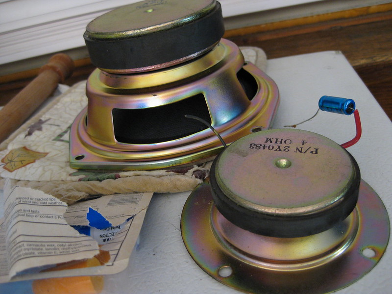
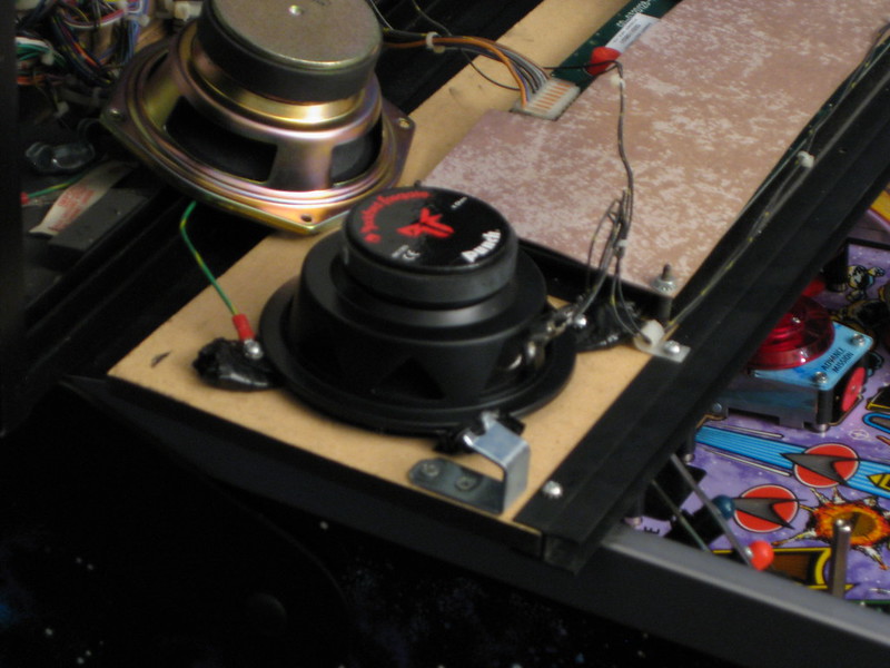
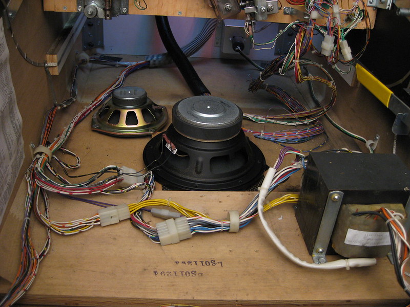
mQ35QBO1putdc0!~~60_12.JPG) The firmer you get the speaker against the surface without air gaps the better, I would use the cardboard from the box as a templet and transfer it to something solid. The speakers dont seem to protrude deeper but Id limit the thickness of what material you use, acrylic plastic? a plastic store could cut out the radius and drill holes for you.
The firmer you get the speaker against the surface without air gaps the better, I would use the cardboard from the box as a templet and transfer it to something solid. The speakers dont seem to protrude deeper but Id limit the thickness of what material you use, acrylic plastic? a plastic store could cut out the radius and drill holes for you.Nice speakers I believe those should be 4 Ohm also
Hey Jeff. There is a guy who can sell me a TNG but he is pretty far away from me and I have no ability to see it in person. I know very little about this machine. Is it ok to PM you some pictures and get your take on them?
If you still need my advice or want to chat about pinball feel free to pm or post or whatever you feel like doing and I'll be happy to tend to it. Thanks for your understanding.